


Contents
Scroll to:
 A. G. Askarova,
A. V. Smirnov,
K. V. Maerle,
E. Y. Popov,
C. Yuan,
D. A. Volkov,
A. A. Ryazanov,
A. N. Cheremisin
A. G. Askarova,
A. V. Smirnov,
K. V. Maerle,
E. Y. Popov,
C. Yuan,
D. A. Volkov,
A. A. Ryazanov,
A. N. Cheremisin https://doi.org/10.18599/grs.2026.2.14
Scroll to:
This study presents a comprehensive experimental and numerical investigation of a promising enhanced oil recovery (EOR) technology based on hydrogen peroxide (H2O2) injection and the initiation of in-situ combustion (ISC). The key advantage of the proposed technology is the ability to initiate high-temperature oil oxidation without surface air injection, as the required oxygen is generated directly within the reservoir through the decomposition of the injected H2O2.
The study included a comparative evaluation of the catalytic activity of iron oxide (Fe2O3) and manganese oxide (MnO2) nanoparticles, as well as an aqueous potassium permanganate (KMnO4) solution for initiating the peroxide decomposition reaction in the reservoir. It was found that under reservoir conditions, the aqueous KMnO4 solution undergoes reduction upon interaction with high-molecular-weight oil components, forming a solid MnO2 phase, thereby becoming immobilized in the pore space and preventing catalyst washout. As a result, the catalytically active layer forms predominantly in oil-saturated zones, localizing heat release during H2O2 decomposition and preventing non-target consumption of the reagent. In laboratory experiments, a maximum temperature of 336°C was achieved, and gas chromatography analysis confirmed the formation of components characteristic of complete oxidation processes, indicating successful ISC initiation. Numerical simulations performed using the CMG STARS software package confirmed the experimental findings, demonstrating that H2O2 decomposition initiates ISC through a sequence of processes: an exothermic peroxide decomposition reaction with significant oxygen release, followed by oil oxidation transitioning into a high-temperature regime with the formation of a stable combustion front. The model accurately reproduces the temperature profiles and gas composition dynamics, allowing the use of obtained kinetic parameters for predictive simulations and optimization of operational parameters.
The implementation of a stable oxidation front driven by oxygen generated from H2O2 decomposition without air injection has been demonstrated. The investigated method represents a promising solution for initiating and maintaining ISC, eliminating the need for complex and costly surface equipment for air or oxygen injection into the reservoir.
Lazarev B.V., Askarova A.G., Smirnov A.V., Maerle K.V., Popov E.Y., Yuan C., Volkov D.A., Ryazanov A.A., Cheremisin A.N. Experimental and Numerical Study of Hydrogen Peroxide Decomposition in the Presence of Catalysts for Enhanced Oil Recovery. Georesursy = Georesources. 2026;28(2):152-167. https://doi.org/10.18599/grs.2026.2.14
The development of heavy oil reservoirs is of strategic importance, as such reserves constitute a significant share of the resource base of the Russian Federation, accounting for approximately 34% (6.3 billion tons) of the currently developed recoverable oil reserves (Paramzin et al., 2024). However, the production of heavy oil requires the implementation of economically efficient technologies, since its high viscosity results in low mobility and reduces the effectiveness of conventional production methods.
Thermal methods have proven to be the most effective approach for reducing oil viscosity and enhancing oil recovery. Conventional thermal enhanced oil recovery (EOR) techniques include hot water injection, steam injection, solvent injection, and in situ combustion (ISC) (Fazlyeva et al., 2023; Yang, Gates, 2009). Hot water injection is characterized by a limited radius of influence due to rapid cooling of the heat carrier in the reservoir (Goodyear et al., 1996; Mukhina et al., 2019; Wu, Liu, 2019). Steam-based methods provide higher temperatures; however, they are associated with significant heat losses, high water and fuel consumption, and the need for steam generation facilities (Alvarado, Manrique, 2010; Lesina, Nikolaeva, 2022). A more technologically complex option is the injection of supercritical water (SCW) to reduce oil viscosity, the application of which is constrained by the requirement for thermally insulated tubing and the development and deployment of specialized surface equipment (Askarova et al., 2020b; Mukhina et al., 2019). The use of solvents is limited by their high cost and losses within the reservoir, making this approach economically unfeasible for large-scale applications (Bayestehparvin et al., 2016; Markovic et al., 2020). ISC enables the maintenance of a stable heat source; however, it requires complex infrastructure for air or oxygen (O2) injection and is associated with technological risks (Askarova et al., 2020a; Maksakov et al., 2021; Moore et al., 2002).
One of the promising directions in the development of thermal EOR methods is the generation of heat directly within the reservoir through the injection of chemical reagents (Anikin et al., 2022; Askarova et al., 2023). Hydrogen peroxide (H2O2), which possesses strong oxidizing properties, can be used as such a reagent. The decomposition of H2O2 releases a significant amount of heat and O2, creating the potential to initiate the ISC process without the need for preliminary heating of the near-wellbore zone or air injection from the surface (Lin, Gurol, 1998; Takagi, Ishigure, 1985). This approach is promising in terms of simplifying surface infrastructure, improving energy efficiency (due to heat generation directly in the reservoir), and potentially achieving more complete oil oxidation through the use of pure O2.
The chemical reaction of H2O2 decomposition proceeds according to the following equation:
H2O2 → H2O + ½O2 + Q (98 kJ/mol).
The O2 released during H2O2 decomposition acts as a pure oxidizing agent, promoting more intensive and higher-temperature oxidation of hydrocarbons compared to conventional air injection, where the O2 content is about 21%. For example, the decomposition of 1 ton of a 50% H2O2 solution produces 165 m³ (at standard conditions) of O2, enabling the generation of a substantial volume of oxidizer directly within the reservoir. In the absence of natural catalysts, H2O2 decomposition under reservoir conditions can be initiated by introducing additional catalysts–transition metal compounds–which enable the onset of a self-sustaining H2O2 decomposition reaction upon contact (Yurasova et al., 2016). Such catalysts may include both soluble compounds (e.g., salt solutions or potassium permanganate) and solid particles, including suspensions of nanoscale metal oxides. The application of nanoparticle suspensions under field conditions is technologically feasible and is already employed in modern EOR methods (Feia et al., 2015; Kaito et al., 2022). The delivery of the suspension to a target reservoir zone is achieved through sequential injection: first, the catalyst suspension is injected, followed by its displacement into the formation by a water slug, which allows the nanoparticles to reach the target interval while minimizing their contact with tubing.
The safety of H2O2-based technology is ensured through careful control of injection parameters H2O2 and catalyst concentrations, injection volume, and injection rate), as these determine the rate of peroxide decomposition and, consequently, the intensity of heat release, gas generation, and pressure increase in the reservoir. To prevent premature decomposition of H2O2 upon contact with the catalyst inside the tubing, it is necessary to separate the injected reagents using buffer volumes of water. In addition, a mandatory step is the preliminary treatment of well equipment with specialized corrosion inhibitors and surface passivators, which reduce the catalytic activity of the metal surfaces and prevent undesired H2O2 decomposition. After inhibitor treatment, the well is flushed to remove excess reagents. A critically important safety measure during H2O2 injection is continuous monitoring using (a) temperature sensors on surface pipelines and, where possible, in the reservoir zone, and (b) a wellhead pressure sensor.
The efficiency of the method is largely determined by the rate, heat release, and completeness of H2O2 decomposition under reservoir conditions, which in turn depend on the activity of the catalyst. At low concentrations of catalytic components in the rock (e.g., iron and manganese oxides and hydroxides) or in formation water, the self-decomposition of H2O2 proceeds slowly and accelerates only at temperatures above 80–100°C. Therefore, the selection of an active and technologically feasible catalyst is a key requirement for the successful implementation of the method (Khlebnikov et al., 2013). Within the framework of this study, a series of preliminary experiments was carried out to evaluate the catalytic activity of various systems, including an aqueous potassium permanganate (KMnO4) solution and suspensions of iron (III) oxide (Fe2O2) and manganese dioxide (MnO2) nanoparticles.
One of the key aspects of the proposed technology is the kinetics of H2O2 decomposition reactions and the subsequent oxidation of hydrocarbons (Antonov et al., 2013). The catalytic decomposition of H2O2 is described by the Arrhenius equation (Askarova et al., 2025b); however, under real reservoir conditions, the process is influenced by heat losses, gas evolution, and side reactions competing with the primary mechanism. Similarly, the oxidation of heavy oil represents a combination of parallel processes, including thermal cracking, low-temperature oxidation (LTO), and high-temperature oxidation (HTO), each characterized by its own activation energy and reaction pathways. The studies by Belgrave and co-authors (Belgrave, 1987; Belgrave et al., 1993; Moore et al., 1996) made a significant contribution to the understanding of these processes. The study by (Moore et al., 1999b) demonstrated that stable combustion can be sustained even at low initial oil saturation, provided that high-temperature reactions dominate, accompanied by carbon bond cleavage and the formation of solid fuel (coke).
The study by (Millour et al., 1987) presented extended kinetic models of LTO for heavy oils and bitumen. Using Athabasca bitumen as an example, three regimes of LTO (22–275°C) were experimentally identified: at the initial stage, only maltenes and asphaltenes are formed; with increasing oxidation degree, coke formation begins; and at the final stage, asphaltenes nearly disappear, with coke being predominantly formed from maltenes. Transitions between these regimes are governed by temperature and O2 partial pressure. A paper by (Moore et al., 1999a) experimentally confirmed the possibility of combining ISC with catalytic upgrading of oil. A laboratory combustion tube experiment (at 325°C in the presence of a NiO/MoO3 catalyst) showed that hydrogen (H2) formed in the gas phase enables upgrading of the displaced oil, reducing its sulfur content, density, and viscosity.
Kinetic modeling of oxidation, validated against laboratory experiments, is an important tool for designing and optimizing ISC processes in real reservoir models. It enables quantitative matching of experimental temperature profiles and gas compositions with the underlying chemical reactions, taking into account the competition between LTO and HTO processes, which differ in activation energy. Such modeling makes it possible to reliably extrapolate laboratory results to field-scale applications and to determine optimal injection parameters for maintaining a stable combustion front.
Previous studies of H2O2 injection have mainly focused on the influence of rock mineral composition, water salinity, and temperature on the decomposition rate of the reagent (Anikin et al., 2022; Askarova et al., 2023). However, experimental validation of the technology accounting for filtration processes remains necessary to reduce uncertainties in subsequent kinetic modeling, catalyst selection, and evaluation of combustion front stability.
The objective of this study is to provide a comprehensive experimental and numerical justification of a technology for initiating self-sustaining ISC through catalytic decomposition of H2O2 under reservoir conditions.
To achieve this objective, the following tasks were addressed:
1. To experimentally evaluate the catalytic activity of various systems (KMnO2, Fe2O3, MnO4) in H2O2 decomposition under conditions close to reservoir conditions;
2. To conduct filtration experiments with measurement of temperature profiles and gas-phase composition to confirm the possibility of initiating self-sustaining ISC;
3. To perform numerical modeling of H2O2 decomposition and heavy oil oxidation using the CMG STARS software, validate the model against experimental data, and assess combustion front stability;
4. To determine the kinetic parameters of H2O2 decomposition and oil oxidation reactions required for the development of reservoir simulation models;
5. To evaluate the applicability of the proposed technology as an alternative to conventional ISC initiation methods without air or O2 injection from the surface.
Thus, this paper presents the results of a comprehensive experimental and numerical study that, for the first time, demonstrates the possibility of initiating self-sustaining ISC solely due to O2 generated from the catalytic decomposition of H2O2 under conditions close to reservoir conditions. Particular attention is given to the comparative analysis of catalytic systems and the validation of the kinetic model in the CMG (Computer Modelling Group) software based on filtration experiment data, ensuring reliable prediction of the technology’s effectiveness for field applications.
To evaluate the applicability of the ISC initiation method using H2O2, a research program was developed that provides a transition from laboratory-scale studies to numerical simulation (Fig. 1). The experiments were carried out using a specialized setup capable of simulating reservoir conditions and controlling process parameters.
The program for the initial validation of the technology on a packed-bed model included three main stages:
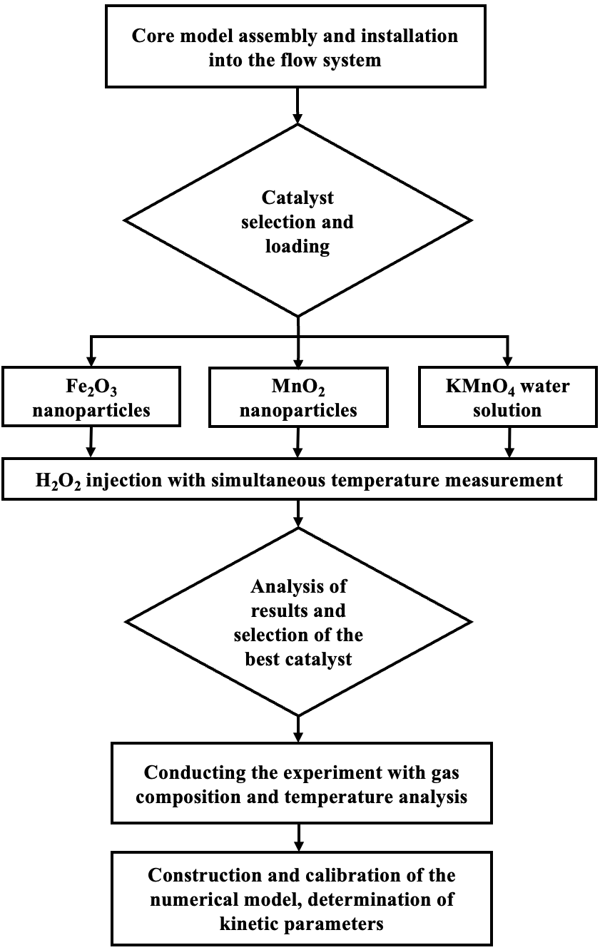
Fig. 1. Block diagram of the research procedure
To address the objectives set, a specialized filtration setup with a flow-through tubular reactor was developed and assembled, enabling the simulation of various injection modes. The setup is designed to operate within a temperature range of 25 to 547 °C and at pressures of up to 17–25 MPa, allowing reproduction of the conditions required for implementing the H2O2 injection technology into the formation. The temperature regime and the dynamics of thermal front propagation in the reactor are monitored using a thermal imager, which ensures precise localization of the reaction zone and continuous measurement of the thermal front propagation velocity.
The setup allows for both thermal and catalytic initiation of the reaction, providing process control, analysis of the component composition of the outlet gases, and collection of liquid fluids in a sealed separator.
A stainless-steel tube with a length of 50 cm and an internal diameter of 21 mm, rated for operation with chemically aggressive media at high temperatures and pressures, was used as the flow-through reactor. To minimize heat losses and enhance safety, the reactor was placed in a thermal insulating casing consisting of an outer metal shell, an inner layer of high-temperature ceramic fiber, and a resilient mineral wool backing. A photograph of the laboratory setup and the flow-through reactor is shown in Fig. 2.
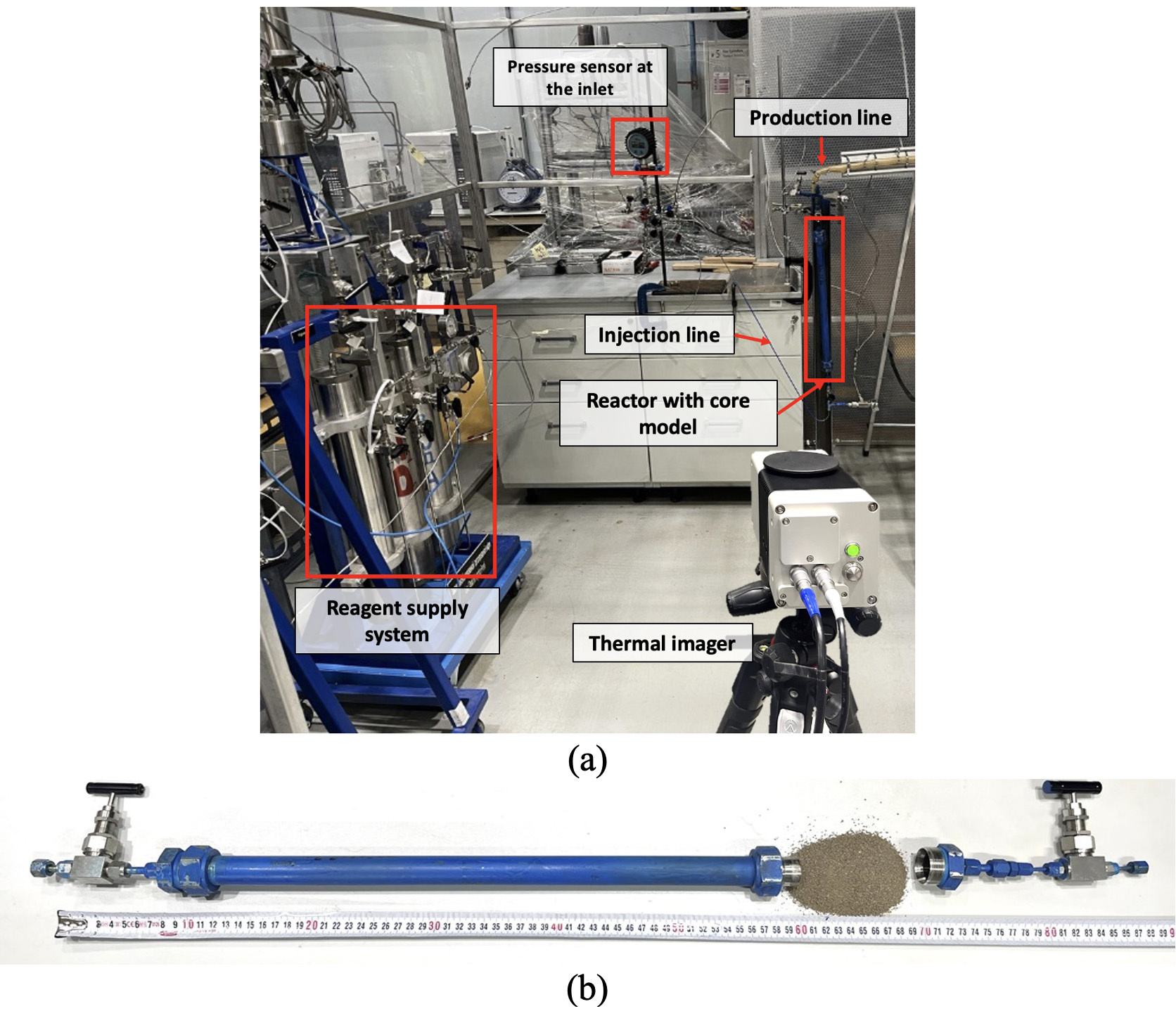
Fig. 2. Laboratory setup: (a) general layout; (b) photograph of the flow-through reactor with the core model
To model the porous medium, crushed core material of a terrigenous rock with a grain size fraction of 0.5–2 mm, sampled from the heavy oil field in the Samara region (Russia), was used. Primary core preparation included extraction in a carbon dioxide (CO2)–toluene extractor, followed by additional extraction with chloroform in a Soxhlet apparatus in accordance with GOST 26450.0-851.
The mineral composition of the rock was determined by X–ray diffraction (XRD) using a Tongda TDM-20 X–ray diffractometer (Bragg–Brentano geometry). The elemental composition was investigated by X–ray fluorescence (XRF) analysis using an Olympus Vanta C portable analyzer. The results of the mineral and elemental composition analysis of the rock are presented in Tables 1 and 2.

Table 1. Results of XRD analysis of the mineral composition of the samples

Table 2. Elemental composition of the main rock-forming minerals
The initial water and oil saturation of the unconsolidated core model was established by sequentially saturating the model with water through the filtration of 2 pore volumes, followed by displacing the water with oil until water production ceased, in order to approximate reservoir conditions. The oil used for saturation was a degassed, anhydrous sample obtained from the field under study, which was laboratory-cleaned of mechanical impurities by filtration through a specialized fine filter2.
The high density and viscosity values classify this crude oil as heavy. At a temperature of 25 °C, the density measured using a Mettler Toledo Excellence D4 hydrometer in accordance with ASTM D 4052 is 0.9234 g/cm3. The viscosity, determined on a Physica MCR 302 rheometer according to ASTM D4440-15, is 166 mPa·s at the same temperature.
Quantitative analysis of the asphaltene content in the original crude oil was performed in accordance with GOST 11858-663 by precipitation in hexane, followed by filtration and solvent evaporation, which ensured high accuracy in measuring its concentration. The determined mass fraction of asphaltenes in the studied crude oil is 7.64%.
The following compositions were used as catalysts for laboratory tests:
The Fe2O3 and MnO2 nanoparticles produced by Shanghai Macklin (China) were loaded into the first fifth of the reactor volume on the injection side as a premix – a suspension consisting of oil, water, and crushed core.
The sequence of the main steps of the laboratory experiments on H2O2 injection is provided below:
1. Assembly of the models and creation of reservoir conditions:
1.1. For the two experiments with MnO2 and Fe2O3 nanoparticles, the first 10 cm of the tubular reactor on the H2O2 injection side were filled with a mixture consisting of crushed extracted core, oil, water, and catalytic nanoparticles; the remaining 40 cm were filled with an identical mixture but without nanoparticles (Fig. 3). The mass fraction of nanoparticles in the mixture was 6%. Then, the pressure in the model was raised to the reservoir pressure by water injection.
1.2. For the experiments with the KMnO4 solution, the tubular reactor was completely filled with crushed extracted core and installed in the flow system (Fig. 4). The pressure was raised to the reservoir pressure of 12 MPa during water filtration (2 pore volumes). Then, 2 pore volumes of oil and 2 pore volumes of a 6% aqueous catalyst solution (KMnO4) were filtered, after which the core model was kept for 48 hours to allow the formation of a solid MnO2 phase at the oil–catalyst solution interface.
2. At the next step, injection of a 50% aqueous H2O2 solution was carried out at a rate of 2 mL/min. For the repeated experiment with the KMnO4 solution, the rate was varied from 2 to 5 mL/min to control the heating rate of the model during the exothermic H2O2 decomposition reaction and to accelerate the transition to the HTO mode.
3. During the H2O2 injection, the temperature of the reactor wall was recorded in real time using a thermal imager. Eight temperature measurement points were taken along the reactor length, with a distance of 5 cm between adjacent points. In the experiment with the KMnO4 solution, the composition of the outlet gas was analyzed by gas chromatography.
4. The onset time of the exothermic reaction, the maximum temperature, and the establishment of a stable self-sustaining H2O2 decomposition mode were determined.
5. When the thermal front had traveled approximately 35–40 cm along the reactor length, the H2O2 injection was stopped.
6. At the final step, water was filtered through the core model to cool the system and displace the combustion products.
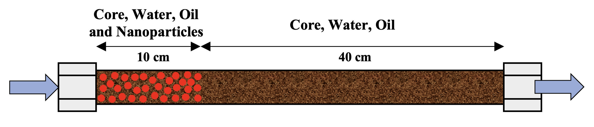
Fig. 3. Core model with nanoparticles in the H2O2 decomposition initiation zone

Fig. 4. Initial core model for experiments with an aqueous KMnO4 solution
To analyze and verify the experimental data, as well as to evaluate the kinetic parameters of the H2O2 decomposition and oil oxidation reactions, numerical modeling of the experiment was performed. The calculations were carried out using the specialized software packages CMG STARS (for thermal process simulation) and CMG CMOST (for history matching). Model calibration was performed against experimental data to compare temperature profiles and outlet gas composition.
The construction of the hydrodynamic model began with creating the core holder geometry based on a Cartesian grid, which offers several advantages over a radial grid. First, the geometric simplicity and regularity of the cells provide high computational efficiency and stability of numerical algorithms. Second, the Cartesian grid allows a more uniform distribution of thermohydrodynamic parameters (temperature, saturation, pressure) within the model. In radial grids, the cell spacing is non-uniform, which shifts the thermal and flow characteristics toward the center of the model – a particularly important factor when describing heat transfer processes.
The constructed numerical model consists of 7 cells in both horizontal directions (i, j) and 49 cells in the vertical direction (k). The external cells corresponding to the model walls have a size of 0.2 cm. The cells in which flow occurs have a vertical size of 1 cm and a horizontal size (in the I and j directions) of 0.372 cm. The distribution of porosity, permeability, and initial oil saturation in the numerical model is shown in Fig. 5. The scale along the longitudinal axis (model length) is reduced by a factor of 1/5 for clarity. H2O2 injection is considered to be uniform across the cross-section and is carried out from bottom to top. The parameters of the numerical model reproducing the average properties of the laboratory core model are presented in Table 3. Relative permeability curves were selected based on experimental data characteristic of the target reservoir. The graphs (Fig. 6) present the relative phase permeabilities of oil (Kro), water (Krw), gas (Krg), and liquid phase (Krl) as functions of water saturation and liquid saturation. The molecular weights of the pseudocomponents are given in Table 4.
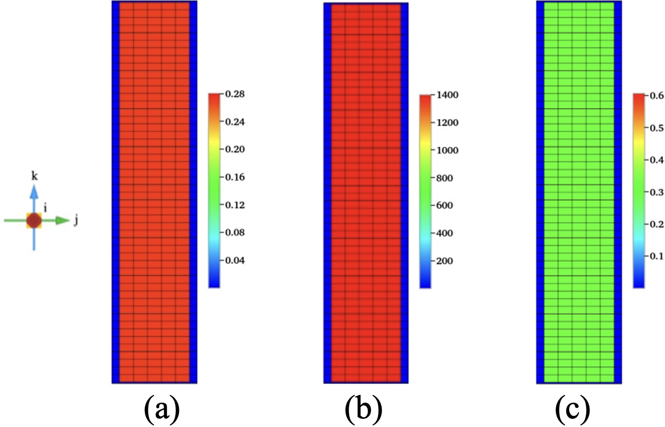
Fig. 5. Distribution of properties in the reactor model constructed on a Cartesian grid: (a) porosity; (b) permeability; (c) initial oil saturation. Length scale 1:5
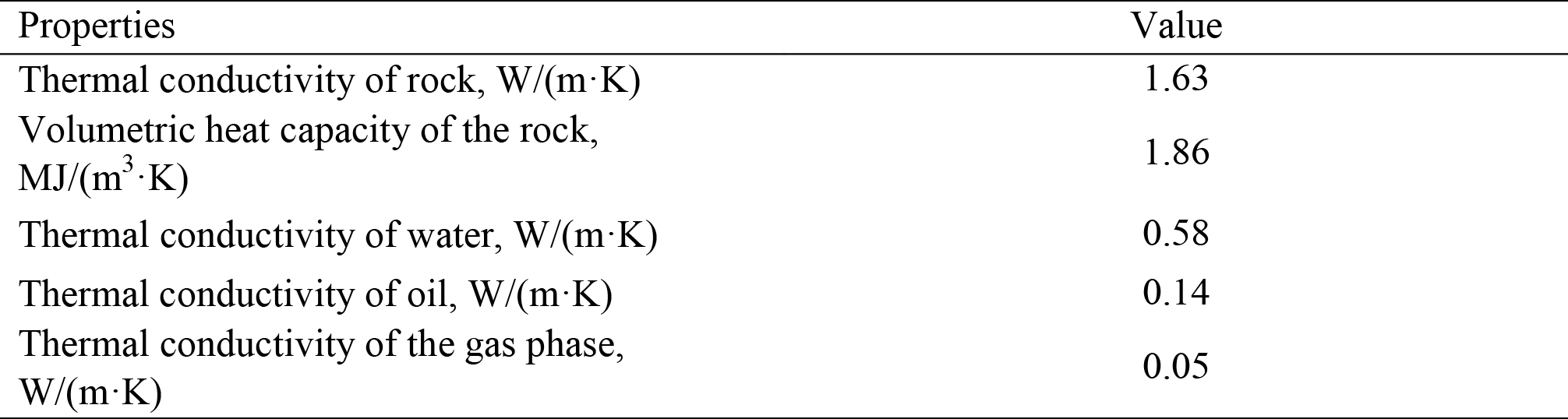
Table 3. Thermal properties of the core, water, oil, and gas phase used in the hydrodynamic model
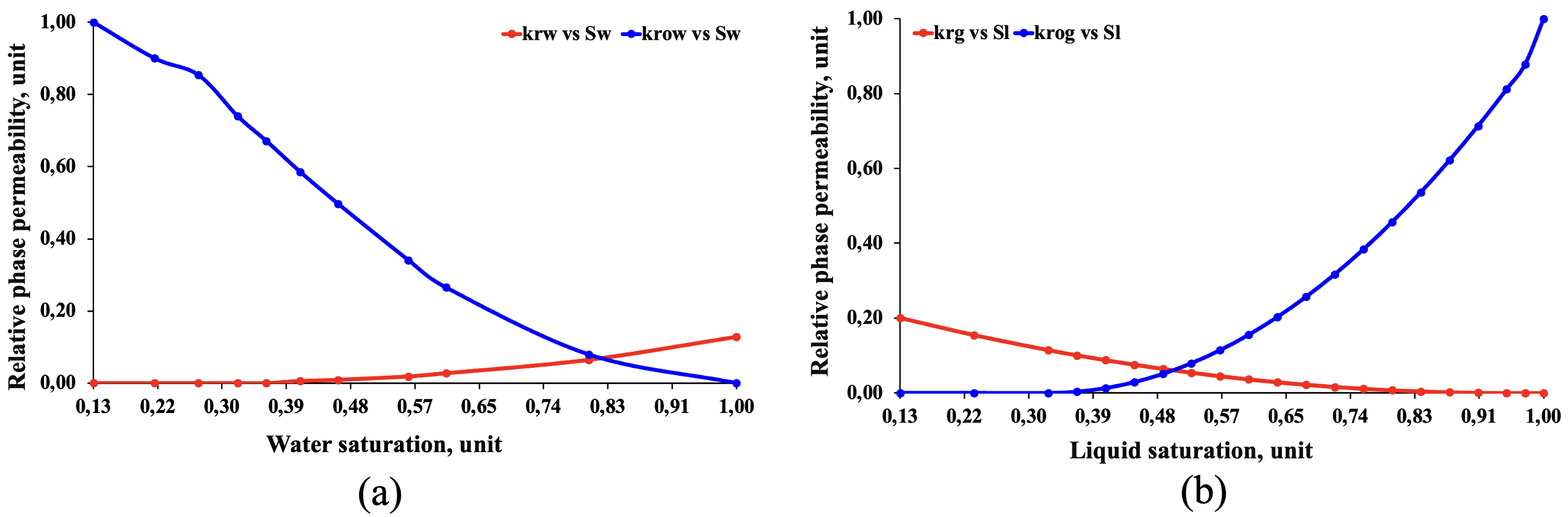
Fig. 6. Relative permeability curves: (a) oil-water system, (b) gas-oil system
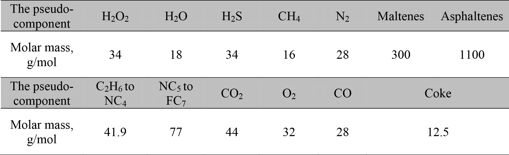
Table 4. Molecular weights of the pseudocomponents used in the hydrodynamic model
The boundary conditions and injection parameters in the numerical model fully corresponded to the experimental setup and the experimental conditions. Injection of a 50% H2O2 solution was simulated at rates identical to the experimental ones, with an initial temperature of 22 °C.
The kinetic model was based on the work of John Belgrave (Belgrave, 1987; Belgrave et al., 1993; Khakimova et al., 2020; Moore et al., 1996), which includes four main oil oxidation reactions: thermal cracking, two LTO reactions, and one HTO reaction. Within the framework of this study, the model was extended by adding the H2O2 decomposition reaction, which made it possible to account for the effect of O2 released in the reservoir on the combustion reactions and the formation of a self-sustaining combustion front.
The first catalysts to undergo laboratory testing in this series of experiments were manganese (IV) oxide (MnO2) and iron (III) oxide (Fe2O3) nanoparticles. Both oxides are active catalysts for H2O2 decomposition (Do et al., 2009). Since the nanoparticles are insoluble in water, their injection into the reservoir is only possible in the form of suspensions. Oil from the target field, mixed with MnO2 or Fe2O3 nanoparticle powder, was used as the dispersion medium. The oil has sufficient viscosity to retain the nanoparticles within its volume, significantly reducing their settling rate. The small particle size of the solid phase ensures suspension stability and enhances its catalytic activity due to the increased specific surface area. Furthermore, the particle size affects the injectivity of the suspension into the reservoir: the smaller the particles, the more easily the suspension penetrates the pore space of the rock. As mentioned earlier, in the experiments conducted, the nanoparticles were added to the reservoir model together with crushed core, water, and oil during the model preparation stage (Fig. 3).
After the experiments with nanoparticles, a liquid catalyst – a 6% aqueous solution of KMnO4 – was tested. KMnO4 is one of the most active chemical reagents accelerating the decomposition of H2O2. It can be applied either as a suspension or as an aqueous solution. The use of an aqueous KMnO4 solution significantly simplifies the preparation and injection process in the field compared to suspensions, reducing the risk of sedimentation and pore space clogging.
In the experiments conducted, H2O2 injection was carried out at a rate of 2 mL/min. The catalyst efficiency was evaluated based on the maximum temperature recorded during the self-sustaining H2O2 decomposition reaction. The temperature profiles for the three experiments are shown in Fig. 7. The results demonstrated that all tested catalysts are capable of initiating H22O2 decomposition with pronounced heat release. However, the 6% aqueous KMnO4 solution exhibited the highest maximum temperature of 280°C, making it the most preferable for field application of the technology. The observed simultaneous temperature rise in zones 2–8 at the time of 40–42 minutes in the KMnO4 experiment is attributed to a change in the injection rate regime.
Based on the data obtained, a 6% aqueous KMnO4 solution was selected for the full cycle of technology verification, including filtration experiments with analysis of gaseous products and subsequent kinetic modeling.
Prior to the filtration experiment, the behavior of the KMnO4 solution upon reaction with oil was studied. In this system, KMnO4 acts as an oxidizer, while the oil acts as a reducing agent. Upon their interaction in a neutral medium, insoluble manganese oxide (MnO2) is formed. The reaction occurs at the phase interface between the aqueous (KMnO4 solution) and the oil phase. To confirm the reaction mechanism, a rapid test was conducted using a KMnO4 solution, the heavy oil from the target field, and a light oil. Test tubes were filled to a height of 10–15 mm with KMnO4 solution, and oil was then poured on top. After two days of standing at room temperature, in the test tube with light oil (Fig. 8, glass tube 4), the formation of a dense plug of manganese dioxide at the phase interface was observed, which retained its shape upon tilting. In the test tubes with heavy oil (glass tubes 2 and 3), the formation of a solid phase was not visually observed; however, the reaction zones were clearly identified by the characteristic staining of the walls.
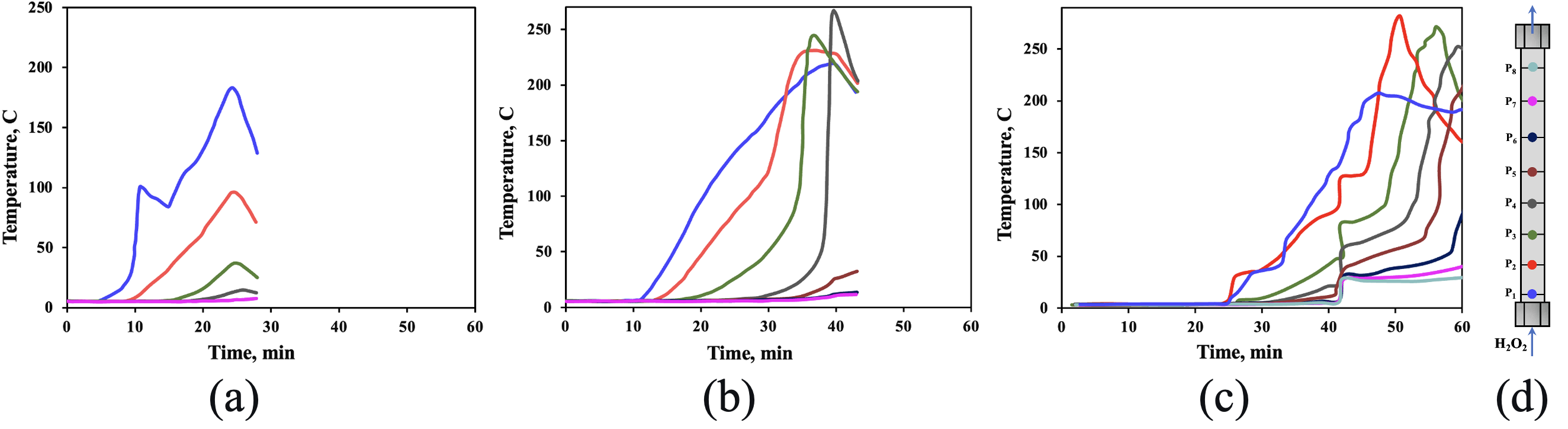
Fig. 7. Temperature profiles of the experiments with (a) Fe2O3; (b) MnO2; (c) KMnO4; (d) location of thermocouples along the reactor length
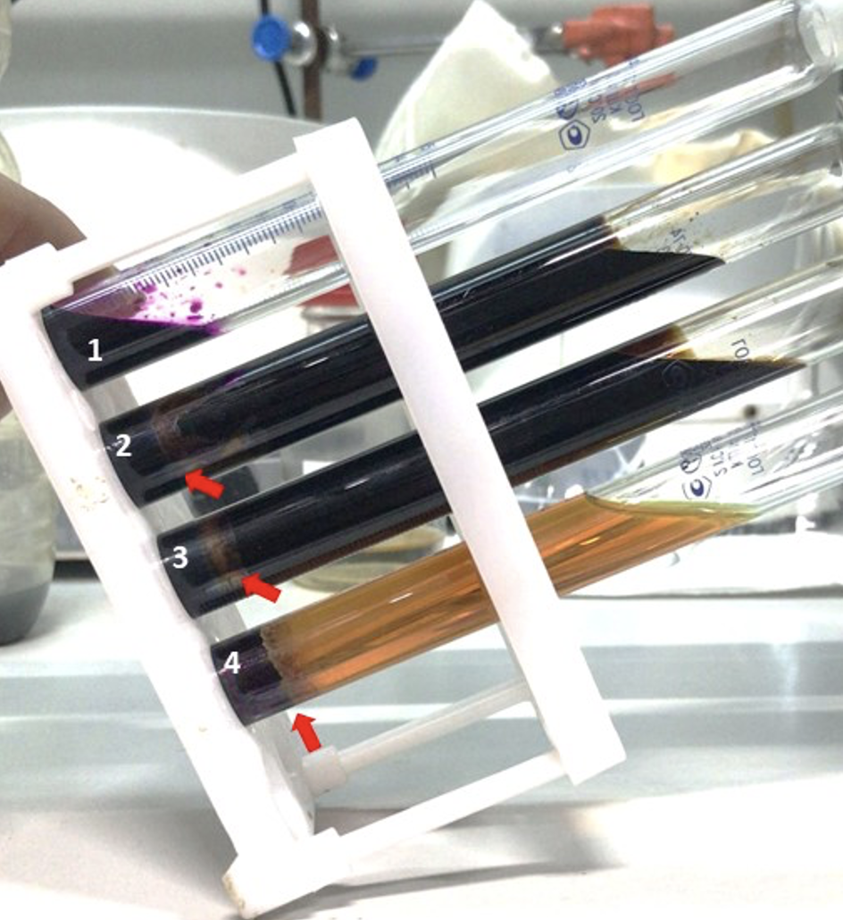
Fig. 8. Glass tubes containing KMnO4 solution (1), heavy oil (2, 3), and light oil (4). The arrows indicate the location of manganese oxide formation at the phase interface
Thus, upon interaction of KMnO4 with oil, a layer of insoluble manganese dioxide is formed, which is an active catalyst for H2O2 decomposition. From a technological standpoint, a holding period is required between the injection of H2O2 and the aqueous KMnO4 solution to allow the reduction reaction to proceed and the formation of an immobilized catalyst layer. The laboratory experiment showed that holding the oil-saturated core model with the injected aqueous KMnO4 solution for 48 hours ensures successful initiation of the self-sustaining H2O2 decomposition reaction.
For full-scale verification of the technology, a filtration experiment was conducted using a 6% aqueous KMnO4 solution. The preparation of the core model and the experimental conditions followed the procedure described: the model was saturated with water and oil from the target field, then two pore volumes of the catalyst were injected, followed by a holding period of two days to allow manganese dioxide to form directly in the porous medium.
Upon injection of a 50% H2O2 solution at a rate of 2 mL/min, the temperature near the injection zone gradually increased to 100°C, corresponding to the initial stage of catalytic H2O2 decomposition (Fig. 9). The initial decrease in O2 concentration in the products is due to the fact that, at the early stage of the experiment, the H2O2 decomposition rate is not yet sufficient to generate significant amounts of O2, and the gas composition at the outlet is primarily determined by the displacement of residual air from the pore space.
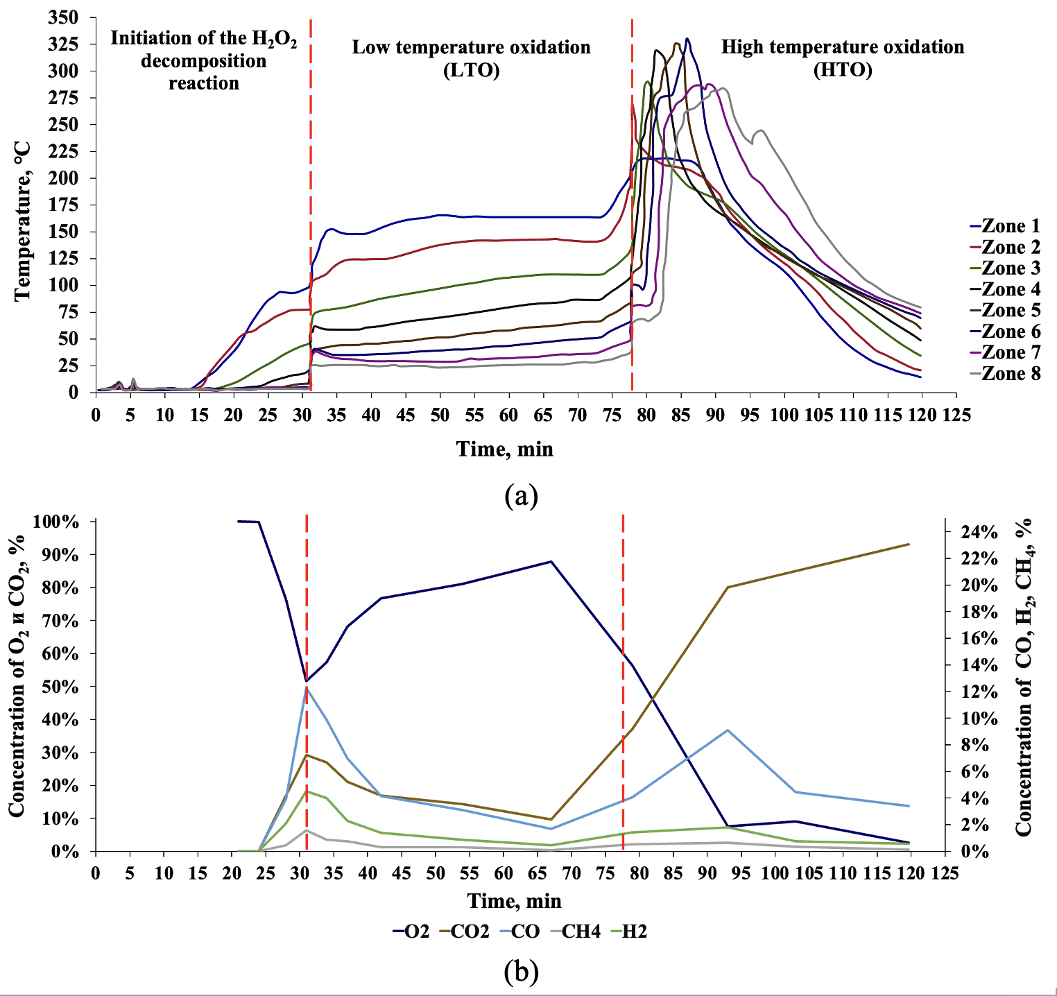
Fig. 9. Graphs of temperature profiles (a) and outlet gas composition (b)
The transition to LTO was accompanied by a temperature increase to 150–200°C and the propagation of the thermal front along the entire length of the reactor. In the gas phase, an increase in O2 concentration to 88% was observed, indicating the onset of self-sustaining H2O2 decomposition. The simultaneous decrease in CO2 content to 10% reflects the dominance of thermal cracking reactions over coke oxidation reactions.
A subsequent increase in the H2O2 injection rate to 5 mL/min at the 72nd minute of the experiment led to an increase in the amount of O2 generated in the model. By this time, the model had already been heated to a temperature (280–300°C) sufficient for the transition to the HTO range, which occurs in the time interval of 75–80 minutes. The transition is accompanied by the attainment of a peak temperature of 330°C and a change in the outlet gas composition. Intensive O2 consumption and an increase in CO2 concentration to 93% are observed. The high carbon dioxide content is due to the occurrence of complete hydrocarbon oxidation reactions, in which O2 is almost entirely consumed to form CO2. The decrease in the O2 fraction in the outlet gas to 2.53% by the end of the experiment demonstrates nearly complete consumption of the O2 released from H2O2 in combustion reactions.
Visual analysis of the core material after the experiment (Fig. 10) showed that in the zones where the high-temperature front had passed, the rock acquired a color close to its original state, indicating the burnout of organic matter. At the same time, at the far end of the reactor, a dark color remained, caused by the presence of residual coke.

Fig. 10. Photograph of the original crushed core (a), the mixture of crushed core, oil, and water before (b) and after (c) the filtration experiment
The experimental results showed that at low H2O2 injection rates, the process proceeds in a controlled LTO mode with moderate heat release, whereas an increase in the flow rate initiates a transition to HTO with intensive O2 consumption. The totality of the obtained data confirms the applicability of H2O2 not only as a source of thermal energy generation in the reservoir, but also as an initiator of ISC processes.
The quantitative results of the numerical model history matching demonstrate a high degree of agreement with the experimental data. The initial calibration of the kinetic parameters was performed taking into account the actual component composition of the reservoir crude oil, which made it possible to correctly reproduce the observed oxidation and combustion processes. The developed kinetic model (Table 5) is based on the calculation of stoichiometric coefficients using molecular weights and the fractional composition of the oil, which ensures material balance and reliable prediction of thermal decomposition under reservoir conditions. This approach enabled a comprehensive description of the behavior of the multiphase system under varying thermobaric parameters, including fluid flow, oil oxidation, heat transfer, and chemical transformation processes.
To explain the catalytic effect observed in the experiment, a reduced activation energy for the H2O2 decomposition reaction was used, as previously determined during experimental studies (Anikin et al., 2022; Askarova et al., 2023). In addition, the pre-exponential factors for both the H2O2 decomposition reaction and the HTO reactions were used as tuning parameters determining the rate and scale of the chemical transformations.
Model calibration showed that reaction No. 3, involving the conversion of asphaltenes to coke, has a significant impact on the overall process, in particular on the further development of the HTO stage. For this reaction, the following orders (degrees of freedom) were assigned: 3 with respect to component O2 and 1 with respect to component Asphaltenes. The relative phase permeabilities were also adjusted in the model to more accurately reproduce the experimental conditions.
History matching of the hydrodynamic model for the H2O2 injection experiment into the core model was performed based on the experimental temperature profiles and the molar fractions of the outlet gases (O2 and CO2), which were used as key indicators of the HTO process.
The determined kinetic parameters of the reactions used in the numerical model are presented in Table 6. It should be noted that the obtained values of the pre-exponential factors and activation energies differ from literature data (Askarova et al., 2025a; Belgrave et al., 1993; Fazlyeva et al., 2023; Khakimova et al., 2020), in particular for reactions 1, 4, and 5 (Table 6), which is due to the consideration of the catalytic effect and the specifics of the laboratory conditions.

Table 5. Chemical reactions used in the model
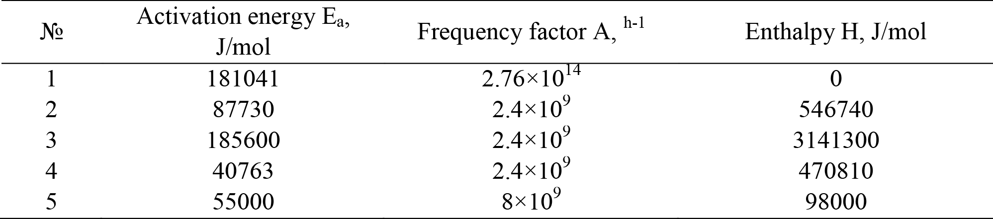
Table 6. Kinetic parameters of the reactions used in the model
Fig. 11 presents the temperature profiles calculated using the CMG STARS software package, compared with the experimental data. The decomposition of H2O2 and the initiation of HTO began in the injection zone (Zone 1), after which the combustion front successively propagated through Zones 2–8. Despite local discrepancies, the verified model reproduces the key characteristics of the process – the timing of the transition to the HTO mode, the spatial distribution of temperature profiles, and the dynamics of combustion front propagation.
To calibrate the parameters of the oxidation reactions, experimental and calculated data on the molar fractions of the evolved gases O2 and CO2 were used (Fig. 12). Overall, the numerical results reproduce the general trends in gas concentration changes: an increase in the O2 fraction at the beginning of the process followed by a decrease, and a mirroring increase in CO2 content as the oxidation reactions develop. At the same time, the temporal concentration peaks in the model occur somewhat earlier than in the experiment, while the maximum O2 and CO2 values in the model are lower and exhibit a smoother character.
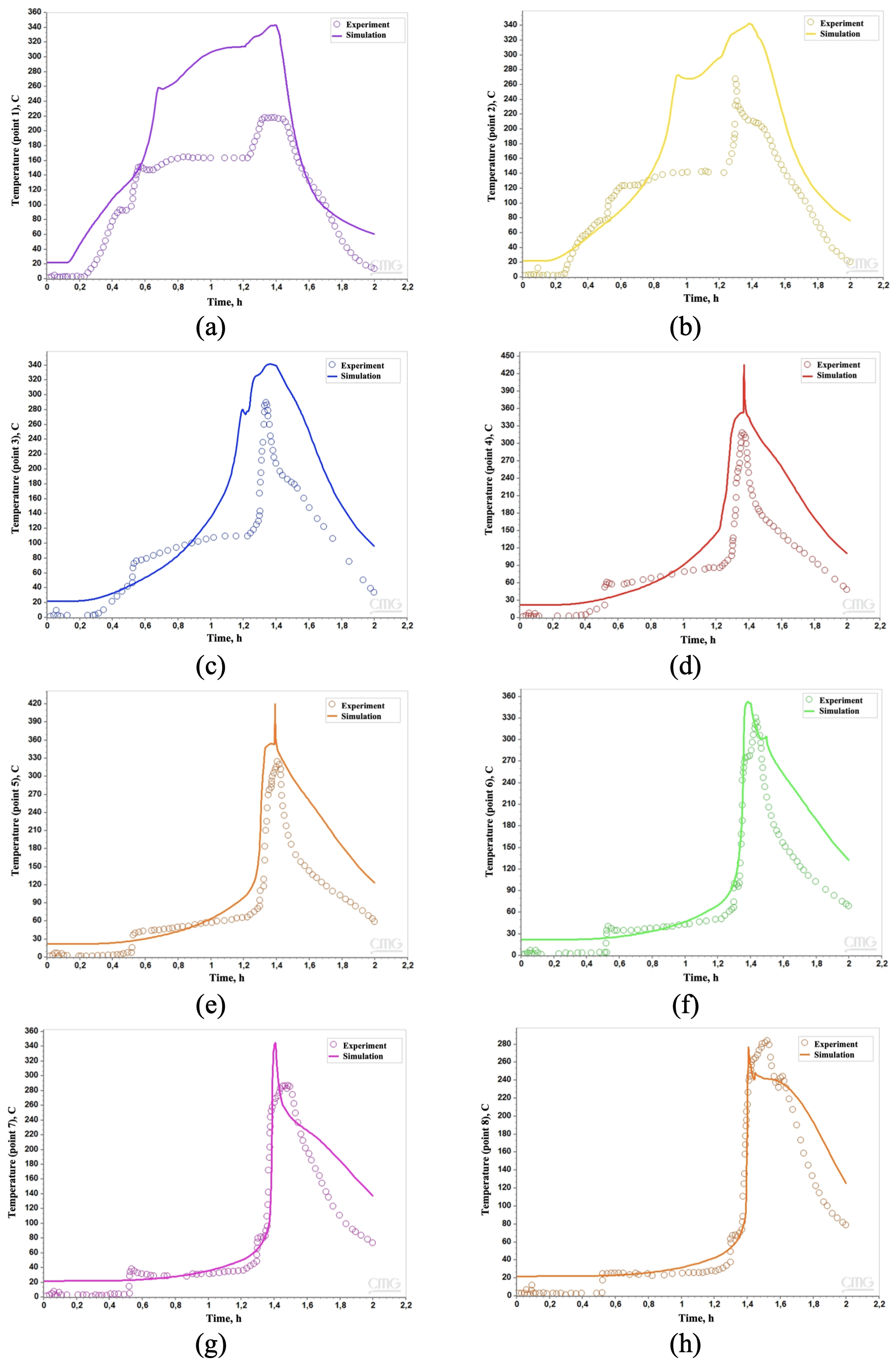
Fig. 11. Comparison of temperature profiles during the experiment and numerical simulation along the reactor length in zones 1 (a), 2 (b), 3 (c), 4 (d), 5 (e), 6 (f), 7 (g), and 8 (h)
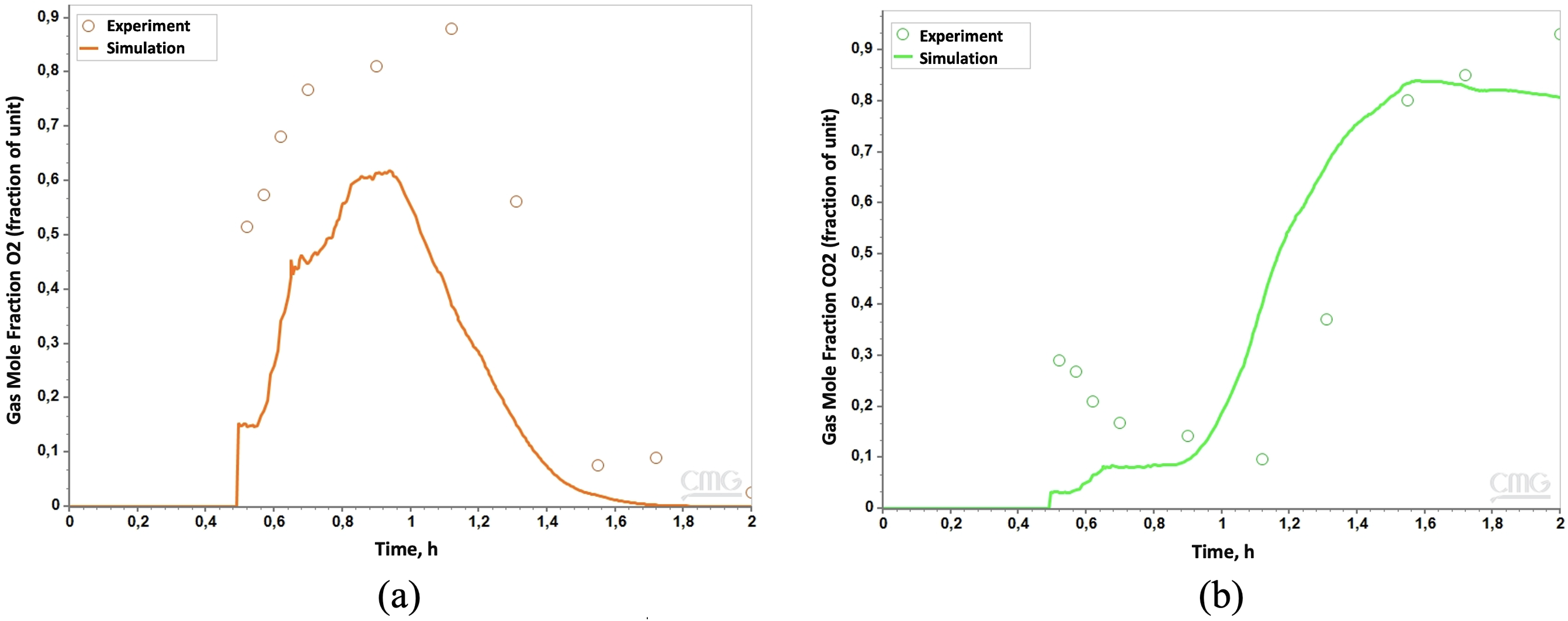
Fig. 12. Comparison of molar fractions obtained during the experiment and numerical simulation: (a) O2, (b) CO2
The noted discrepancies are explained by the simplifying assumptions of the numerical scheme – idealized reaction kinetics, homogeneity of model properties, and the absence of mass transfer limitations. In the model, the transfer of O2 between phases is assumed to be instantaneous, whereas in the experiment, part of the O2 may remain dissolved or be locally retained in the pores, which delays its participation in the reactions and leads to a lag in reaching peak concentrations. Furthermore, the uniform distribution of the catalyst and the neglect of heat losses in the model result in a more uniform progression of the reactions and, consequently, a smoothing of the O2 and CO2 concentration curves. Despite these discrepancies, the numerical model reliably reproduces the main trends in the gas phase composition and thermal regime.
Fig. 13 shows a comparison of the thermal imager data and the numerical simulation results of the temperature distribution in the reactor at the moment of HTO development. Excellent correspondence in the propagation velocities of the combustion front is observed, indicating the correctness of the calculations. A slight overestimation of the temperatures obtained from the numerical calculations may be due to the fact that the thermal imager records the temperature on the outer surface of the reactor wall, whereas in the model the temperature is calculated inside the reactor, in the reaction zone.
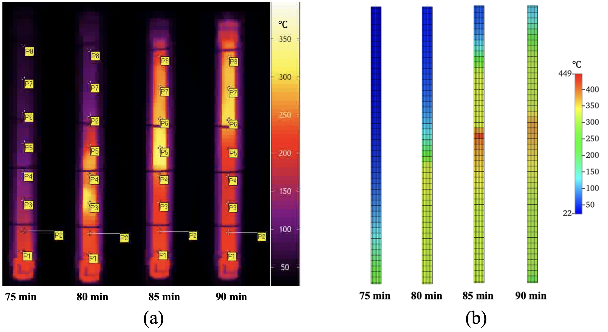
Figure 13. Comparison of the reactor wall temperature measured by the thermal imager (a) with the temperature in the model (b)
Thus, despite the noted discrepancies, the numerical model implemented in the CMG STARS package adequately describes the overall dynamics of the process and can be used to predict system behavior under varying technological parameters. Improving the accuracy of the simulation is possible by refining the kinetic constants, accounting for heat losses, and developing models that reflect the non-uniform distribution of the catalyst along the reactor length.
The experiments showed that when an aqueous KMnO4 solution is injected into oil-saturated core models of the reservoir, an initial temperature increase near the reagent injection zone is observed, associated with the decomposition of H2O2. Upon reaching a temperature of 100–120°C, the oil oxidation process is initiated (Fig. 9), accompanied by intense heat release. The maximum recorded temperature on the outer surface of the reactor was 336°C, indicating even higher values inside the reactor.
Analysis of the outlet gas composition by gas chromatography showed a sequential change in component composition as the temperature increased. Due to the small volume of the outlet stream, gas samples were collected into special gas sampling bags, followed by analysis of the samples in a gas chromatograph to determine the component composition. At the initial stage, corresponding to H2O2 decomposition, the main component is O2. As the reaction progresses, LTO products, including H2, CO, CO2, and CH4, are detected, while the O2 fraction reaches 90%. With a further increase in temperature, the O2 content decreases, and the CO2 fraction increases, reaching 93% (Fig. 9(b)), indicating the transition of the process to the ISC stage.
Within the framework of this study, a comprehensive experimental and numerical simulation study was performed to develop and verify a technology for initiating ISC using H2O2 as a source of O2 and thermal energy.
Comparative tests of three types of H2O2 decomposition catalysts – Fe2O3 and MnO2 nanoparticles, as well as an aqueous KMnO4 solution – demonstrated their ability to initiate H2O2 decomposition with a transition to a self-sustaining mode. The highest efficiency was shown by a 6% aqueous KMnO4 solution, with which a maximum temperature of 336°C was achieved in the filtration experiment. Its mechanism of action, based on reduction to solid MnO2 directly at the oil–water interface, provides localized and stable catalytic action, eliminating the risks of sedimentation and formation clogging characteristic of nanoparticle suspensions.
Gas chromatographic analysis of the reaction products and temperatures in the core model during the KMnO4 experiment confirmed the occurrence of complete hydrocarbon oxidation stages up to ISC. A transition in oxidation regimes was recorded: from LTO, accompanied by the release of CO2 and light hydrocarbons, to HTO with a sharp consumption of O2 and an increase in CO2 concentration to 93%. This indicates complete utilization of the O2 released from H2O2 decomposition in hydrocarbon oxidation reactions.
The verified numerical model, implemented in the CMG STARS software package, including the H2O2 decomposition reaction and a set of oil oxidation reactions, adequately reproduces the key features of the process: temperature profiles, combustion front propagation dynamics, and changes in the outlet gas composition. The observed discrepancies (an earlier transition to the HTO stage in the model) are associated with simplifications such as uniform catalyst distribution and idealized heat and mass transfer conditions. The simulation results confirmed the conclusions of the experimental studies that H2O2 decomposition initiates the development of oxidation reactions and the formation of a stable combustion front analogous to that produced by air injection.
The obtained set of kinetic parameters (activation energies, pre-exponential factors) provides a basis for constructing a hydrodynamic model of the development of the target field. This creates the prerequisites for transitioning from the laboratory stage to predictive calculations aimed at optimizing injection parameters (reagent concentrations, volumes, and rates) and assessing the technological and economic efficiency of the method under the specific geological and physical conditions of the target reservoir.
Thus, the results have shown that H2O2 decomposition in the presence of a suitable catalyst can initiate and sustain stable ISC without the need for air or O2 injection from the surface. This is confirmed by the combination of laboratory filtration experiments and numerical simulation, ensuring high reliability of the obtained results. The investigated EOR technology represents an effective and promising solution for initiating ISC, particularly in heavy oil fields where traditional methods are limited by technological and economic factors.
The authors are grateful to their colleagues from the Center for Hydrocarbon Recovery Science and Technology at the Skolkovo Institute of Science and Technology: engineer Nikolay Taraskin and deputy laboratory director Pavel Grishin for their assistance in conducting the experiments.
1GOST 26450.0-85. Mountain rocks. Methods for determining reservoir properties. Moscow: Publishing House of Standards, 1985. p. 4.
2GOST 39-235-89. 1989. Oil. A method for determining relative phase permeability during joint stationary filtration of oil and water. Departmental standard. M., 1989. p. 24.
3GOST 11858-66. 1987. Oil and petroleum products. Method for determining the content of asphalt-resinous substances. M.: Publishing House of Standards, 1987.
1. Alvarado V., Manrique E. (2010). Enhanced Oil Recovery: An Update Review. Energies, pp. 1529–1575. https://doi.org/10.3390/en3091529
2. Anikin O.V. et al. (2022). Factors influencing hydrogen peroxide decomposition dynamics for thermochemical treatment of bottomhole zone. Journal of Petroleum Exploration and Production Technology, 12(9), pp. 2587–2598. https://doi.org/10.1007/s13202-022-01507-z
3. Antonov, S.V., Zobov, P.M., Bakulin, D.A., Bardin, M.E., Khlebnikov, V.N. (2013). Assessment of prospects for hydrogen peroxide in the thermal methods of viscous oil production. Bashkirskii khimicheskii zhurnal, 2, pp. 5–11. (In Russ.)
4. Askarova A. et al. (2020a). Evaluation of the subject geological area suitability for oil recovery by High-Pressure Air Injection method. Advances in Geosciences, 54, pp. 7–14. https://doi.org/10.5194/adgeo-54-7-2020
5. Askarova A. et al. (2020b). Unconventional Reservoirs: Methodological Approaches for Thermal EOR Simulation. SPE/AAPG/SEG Unconventional Resources Technology Conference, D033S086R002. https://doi.org/10.15530/urtec-2020-2112
6. Askarova A. et al. (2025a). Innovative technology for underground clean in situ hydrogen generation: Experimental and numerical insights for sustainable energy transition. Renewable Energy, 240. https://doi.org/10.1016/j.renene.2024.122259
7. Askarova A. et al. (2023). Perspectives of Hydrogen Peroxide Injection to the Carbonate Reservoir for ISC Initiation. Society of Petroleum Engineers – ADIPEC, ADIP 2023 [Preprint]. https://doi.org/10.2118/216649-MS
8. Askarova A. et al. (2025b). Experimental Validation of Hydrogen Peroxide Injection for Heavy Oil Recovery: Insights from Medium-Scale Combustion Tube Test. Middle East Oil, Gas and Geosciences Show (MEOS GEO), D011S007R006. https://doi.org/10.2118/227279-MS
9. Bayestehparvin B., Ali S.M.F. and Abedi J. (2016). Use of Solvents With Steam – State-of-the-Art and Limitations Why Use Solvents? Solvents vs. Heat for Oil Viscosity Reduction. SPE EOR Conference, (March), pp. 1–31. https://doi.org/10.2118/179829-MS
10. Belgrave J.D.M. (1987). An experimentsl and Numerical Investigation of In-situ Combustion Tube Tests.
11. Belgrave J. et al. (1993). A Comprehensive Approach to In-Situ Combustion Modeling. SPE Advanced Technology Series, 1(01), pp. 98–107. https://doi.org/10.2118/20250-PA
12. Do S.-H. et al. (2009). Hydrogen peroxide decomposition on manganese oxide (pyrolusite): kinetics, intermediates, and mechanism. Chemosphere, 75(1), pp. 8–12. https://doi.org/10.1016/j.chemosphere.2008.11.075
13. Fazlyeva R. et al. (2023). In situ combustion. in A. Hemmati-Sarapardeh et al. (eds.) Thermal Methods. Gulf Professional Publishing, pp. 155–215. https://doi.org/10.1016/B978-0-12-821933-1.00007-0
14. Feia S. et al. (2015). Experimental investigation of particle suspension injection and permeability impairment in porous media. Geomechanics for Energy and the Environment, 3, pp. 24–39. https://doi.org/https://doi.org/10.1016/j.gete.2015.07.001
15. Goodyear S. et al. (1996). Hot water flooding for high permeability viscous oil fields. in Proceedings – SPE Symposium on Improved Oil Recovery, pp. 289–299. Available at: https://doi.org/10.2118/35373-ms
16. Kaito Y. et al. (2022). First Nanoparticle-Based EOR Nano-EOR Project in Japan: Laboratory Experiments for a Field Pilot Test. https://doi.org/10.2118/209467-MS
17. Khakimova L. et al. (2020). High-pressure air injection laboratory-scale numerical models of oxidation experiments for Kirsanovskoye oil field. Journal of Petroleum Science and Engineering, 188, 106796. https://doi.org/10.1016/J.PETROL.2019.106796
18. Khlebnikov, V.N., Vinokurov, V.A., Zobov, P.M., Gushchina, Y.F., Mishin, A.S., Antonov, S.V. (2013). New method of thermal treatment of the well bottom zone using hydrogen peroxide. Patent RU2534870C2. (In Russ.)
19. Lesina, N.V., Nikolaeva, S.N. (2022). Development of high-viscosity oil deposits by pumping coolant into a horizontal well with preliminary steam cycle treatments. Neftepromyslovoe delo, 7(643), pp. 34–43. (In Russ.) DOI: 10.33285/0207-2351-2022-7(643)-39-43
20. Lin S., Gurol M. (1998). Catalytic Decomposition of Hydrogen Peroxide on Iron Oxide: Kinetics, Mechanism, and Implications. Environmental Science & Technology, 32(10), pp. 1417–1423. https://doi.org/10.1021/es970648k
21. Maksakov K., Lesina N. and Schekoldin K. (2021). Approach to hydrodynamic modeling of in-situ combustion in carbonate reservoir based on the results of laboratory studies and preliminary works for pilot test. Society of Petroleum Engineers – SPE Russian Petroleum Technology Conference 2021, RPTC 2021 [Preprint]. https://doi.org/10.2118/SPE-206546-MS
22. Markovic S. et al. (2020). In-situ heavy oil viscosity prediction at high temperatures using low-field NMR relaxometry and nonlinear least squares. Fuel, 260. https://doi.org/10.1016/j.fuel.2019.116328
23. Millour J. et al. (1987). An Expanded Compositional Model For Lowtemperature Oxidation Of Athabasca Bitumen. Journal of Canadian Petroleum Technology, 26(03). https://doi.org/10.2118/87-03-02
24. Moore R. et al. (1996). Combustion/Oxidation Behavior of Athabasca Oil Sands Bitumen. Improved Oil Recovery Symposium. Society of Petroleum Engineers, pp. 1–8. https://doi.org/10.2118/35392-MS
25. Moore R., Mehta S., and Ursenbach M. (2002). A Guide to High Pressure Air Injection (HPAI) Based Oil Recovery. SPE/DOE Improved Oil Recovery Symposium. https://doi.org/10.2118/75207-ms
26. Moore R., Laureshen C., et al. (1999a). A Downhole Catalytic Upgrading Process for Heavy Oil Using In Situ Combustion. Journal of Canadian Petroleum Technology, 38(13). https://doi.org/10.2118/99-13-44
27. Moore R., Belgrave J., et al. (1999b). In Situ Combustion Performance in Steam Flooded Heavy Oil Cores The University of Calgary. Journal of Canadian Petroleum Technology, 38(13).
28. Mukhina E. et al. (2019). Hydrocarbon Saturation for an Unconventional Reservoir in Details. SPE Russian Petroleum Technology Conference, D033S024R004. https://doi.org/10.2118/196743-MS
29. Paramzin, A.R., Zinoviev, A.M., Kanaikin, I.E., Ziganshin, R.S., Davydov, M.A., Margachev, D.A. (2024). The Current State Of The World’s Reserves Of High-Viscosity Oil And Natural Bitumen. Vestnik Evraziyskoy Nauki, 16, pp. 1–13. (In Russ.)
30. Takagi J., Ishigure K. (1985). Thermal Decomposition of Hydrogen Peroxide and Its Effect on Reactor Water Monitoring of Boiling Water Reactors. Nuclear Science and Engineering, 89(2), pp. 177–186. https://doi.org/10.13182/NSE85-A18191
31. Wu Z., Liu H. (2019). Investigation of hot-water flooding after steam injection to improve oil recovery in thin heavy-oil reservoir. Journal of Petroleum Exploration and Production Technology, 9(2), pp. 1547–1554. https://doi.org/10.1007/s13202-018-0568-7
32. Yang X., Gates I.D. (2009). Combustion kinetics of Athabasca bitumen from 1D combustion tube experiments. Natural Resources Research, 18(3), pp. 193–211. https://doi.org/10.1007/s11053-009-9095-z
33. Yurasova I., Yurasov N. and Sulegin D. (2016). Study of Potassium Dichromate-Catalyzed Hydrogen Peroxide Decomposition. Herald of the Bauman Moscow State Technical University. Series Natural Sciences [Preprint]. https://doi.org/10.18698/1812-3368-2016-5-125-135
Bogdan V. Lazarev – Master’s Student, Center for Hydrocarbon Recovery Science and Technology
Moscow
Aisylu G. Askarova – Senior Research Scientist, Center for Hydrocarbon Recovery Science and Technology
Moscow
Alexey V. Smirnov – Postgraduate Student, Center for Hydrocarbon Recovery Science and Technology
Moscow
Kirill V. Maerle – Research Scientist, Center for Hydrocarbon Recovery Science and Technology
Moscow
Evgeny Yu. Popov – Head of the Thermal EOR Laboratory, Center for Hydrocarbon Recovery Science and Technology
Moscow
Chengdong Yuan – Associate Professor, Center for Hydrocarbon Recovery Science and Technology
Moscow
Dmitry A. Volkov – Senior Manager, Innovation Development Department
Moscow
Arsentiy A. Ryazanov – Head of Enhanced Oil Recovery Department
Volgograd
Alexey N. Cheremisin – Professor, Center for Hydrocarbon Recovery Science and Technology
Moscow
Lazarev B.V., Askarova A.G., Smirnov A.V., Maerle K.V., Popov E.Y., Yuan C., Volkov D.A., Ryazanov A.A., Cheremisin A.N. Experimental and Numerical Study of Hydrogen Peroxide Decomposition in the Presence of Catalysts for Enhanced Oil Recovery. Georesursy = Georesources. 2026;28(2):152-167. https://doi.org/10.18599/grs.2026.2.14
 Email this article (Login required)
Email the author (Login required)
Email this article (Login required)
Email the author (Login required) Address of the Editorial Office: Ametievskaya magistral st., 18, build. 2, ap. 3, Kazan, Republic of Tatarstan, 420087, Russian Federation
Contacts of the Editorial Office: Phone: +7 927 039-05-30, e-mail: mail@geors.ru
Founder: Daria A. Khristoforova
Publisher: Georesursy LLC







.png)

